DTC B2799 Engine Immobiliser System Malfunction |
| DTC No. | DTC Detection Condition | Trouble Area |
| B2799 | One of the following conditions is met:
|
|
| w/o Airbag Cut-off Switch |
| w/ Airbag Cut-off Switch |
| 1.CHECK DTC OUTPUT |
Clear the DTCs (Click here).
Recheck for DTCs (Click here).
|
| ||||
| OK | ||
| ||
| 2.RE-REGISTER ECU COMMUNICATION ID |
Re-register the ECU communication ID.
| NEXT | |
| 3.CHECK DTC OUTPUT |
Clear the DTCs (Click here).
Recheck for DTCs (Click here).
|
| ||||
| OK | ||
| ||
| 4.CHECK CONNECTOR CONNECTION CONDITION |
Turn the power switch off.
Check that the connectors are properly connected to the power management control ECU (HV CPU) and certification ECU (smart key ECU assembly)*1 or ID code box (immobiliser code ECU)*2.
|
| ||||
| OK | |
| 5.SYSTEM CHECK |
Check the vehicle specification.
| Result | Proceed to |
| w/o Airbag Cut-off Switch | A |
| w/ Airbag Cut-off Switch | B |
|
| ||||
| A | |
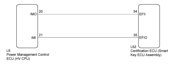
| 6.CHECK HARNESS AND CONNECTOR (CERTIFICATION ECU - POWER MANAGEMENT CONTROL ECU (HV CPU)) |
Disconnect the certification ECU (smart key ECU assembly) connector.
 |
Disconnect the power management control ECU (HV CPU) connector.
Measure the resistance and voltage according to the value(s) in the table below.
| Tester Connection | Condition | Specified Condition |
| L62-34 (EFII) - L6-20 (IMO) | Always | Below 1 Ω |
| L62-35 (EFIO) - L6-21 (IMI) | Always | Below 1 Ω |
| L6-20 (IMO) - Body ground | Always | 10 kΩ or higher |
| L6-21 (IMI) - Body ground | Always | 10 kΩ or higher |
| Tester Connection | Condition | Specified Condition |
| L6-20 (IMO) - Body ground | Always | Below 1 V |
| L6-21 (IMI) - Body ground | Always | Below 1 V |
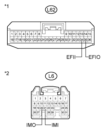
| *1 | Front view of wire harness connector (to Certification ECU (Smart Key ECU Assembly)) |
| *2 | Front view of wire harness connector (to Power Management Control ECU (HV CPU)) |
|
| ||||
| OK | |
| 7.REPLACE POWER MANAGEMENT CONTROL ECU (HV CPU) |
Replace the power management control ECU (HV CPU) (Click here).
| NEXT | |
| 8.CHECK DTC OUTPUT |
Clear the DTCs (Click here).
Recheck for DTCs (Click here).
|
| ||||
| OK | ||
| ||
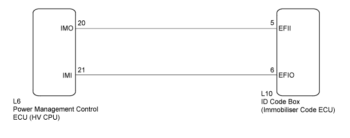
| 9.CHECK HARNESS AND CONNECTOR (ID CODE BOX - POWER MANAGEMENT CONTROL ECU (HV CPU)) |
Disconnect the ID code box (immobiliser code ECU) connector.
 |
Disconnect the power management control ECU (HV CPU) connector.
Measure the resistance and voltage according to the value(s) in the table below.
| Tester Connection | Condition | Specified Condition |
| L10-5 (EFII) - L6-20 (IMO) | Always | Below 1 Ω |
| L10-6 (EFIO) - L6-21 (IMI) | Always | Below 1 Ω |
| L6-20 (IMO) - Body ground | Always | 10 kΩ or higher |
| L6-21 (IMI) - Body ground | Always | 10 kΩ or higher |
| Tester Connection | Condition | Specified Condition |
| L6-20 (IMO) - Body ground | Always | Below 1 V |
| L6-21 (IMI) - Body ground | Always | Below 1 V |
| *1 | Front view of wire harness connector (to ID Code Box (Immobiliser Code ECU)) |
| *2 | Front view of wire harness connector (to Power Management Control ECU (HV CPU)) |
|
| ||||
| OK | |
| 10.REPLACE POWER MANAGEMENT CONTROL ECU (HV CPU) |
Replace the power management control ECU (HV CPU) (Click here).
| NEXT | |
| Go to step 7 |
| 11.CHECK DTC OUTPUT |
Clear the DTCs (Click here).
Recheck for DTCs (Click here).
|
| ||||
| OK | ||
| ||
