THERMOSTAT > INSTALLATION |
| 1. INSTALL WATER INLET WITH THERMOSTAT SUB-ASSEMBLY |
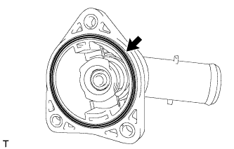 |
Install a new gasket on the water inlet with thermostat sub-assembly.
 |
Install the water inlet with thermostat sub-assembly with the 2 nuts and bolt.
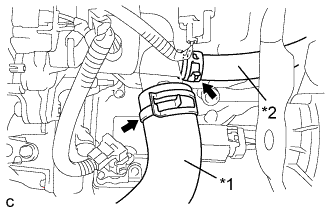 |
Connect the No. 2 radiator hose and No. 3 water by-pass hose.
| *1 | No. 2 Radiator Hose |
| *2 | No. 3 Water By-pass Hose |
| 2. ADD COOLANT (for Engine) |
Tighten the radiator drain cock plug.
Remove the reservoir tank cap.
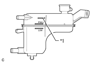 |
Add coolant to B line of the reservoir tank.
| *1 | B Line |
| Item | Capacity |
| Engine coolant | w/ Exhaust Heat Recirculation System: 7.2 liters (7.6 US qts, 6.3 lmp. qts) |
| w/o Exhaust Heat Recirculation System: 6.5 liters (6.8 US qts, 5.7 lmp. qts) |
Squeeze the inlet and outlet radiator hoses several times by hand, and then check the level of the coolant.
If the coolant level is low, add coolant.
Install the reservoir tank cap.
Put the engine in inspection mode (Click here).
Bleed air from the cooling system.
Warm up the engine until the thermostat opens. While the thermostat is open, allow the coolant to circulate for several minutes.
Squeeze the inlet and outlet radiator hoses several times by hand to bleed air from the system.
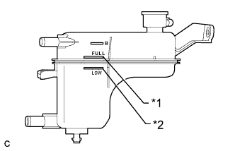 |
After the engine has cooled down, check that the coolant level is between full and low.
| *1 | Full Line |
| *2 | Low Line |
| 3. INSPECT FOR COOLANT LEAK (for Engine) |
Remove the reservoir tank cap.
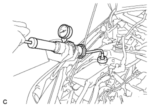 |
Fill the radiator and reservoir with coolant, and then attach a radiator cap tester.
Put the engine in inspection mode (Click here).
Warm up the engine.
Using the reservoir cap tester, increase the pressure inside the radiator to 108 kPa (1.1 kgf/cm2, 16 psi), and check that the pressure does not drop. If the pressure drops, check the hoses, radiator, front exhaust pipe assembly and the heater hose around and engine water pump assembly for leaks. If no external leaks are found, check the heater core, cylinder block and cylinder head.
Remove the radiator cap tester.
Install the reservoir tank cap.
| 4. INSTALL ENGINE OIL LEVEL DIPSTICK GUIDE SUB-ASSEMBLY |
Apply a light coat of engine oil to a new O-ring.
Install the O-ring to the engine oil level dipstick guide.
 |
Install the engine oil level dipstick guide with the 2 bolts.
Connect the clamp to the engine oil level dipstick guide.
Install the engine oil level dipstick.
| 5. INSTALL INLET AIR CLEANER ASSEMBLY |
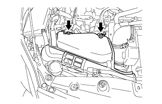 |
Install the inlet air cleaner assembly with the 2 bolts.
| 6. INSTALL ENGINE UNDER COVER |
| 7. INSTALL FRONT SPOILER COVER (w/ Front Spoiler) |
