CRUISE CONTROL SYSTEM > Cruise Control Switch Circuit |
| 1.READ VALUE USING INTELLIGENT TESTER |
 |
Connect the intelligent tester to the DLC3.
Turn the power switch on (IG).
Turn the intelligent tester on.
Enter the following menus: Powertrain / Cruise Control / Data List.
Check the Data List for proper functioning of the cruise control main switch.
| Tester Display | Measurement Item/Range | Normal Condition | Diagnostic Note |
| Main SW M-CPU | Cruise control switch (Main CPU)/ON or OFF | ON: Cruise main switch on OFF: Cruise main switch off | - |
| Cancel Switch | CANCEL switch signal/ON or OFF | ON: CANCEL switch on OFF: CANCEL switch off | - |
| SET/COAST Switch | - SET switch signal/ON or OFF | ON: - SET switch on OFF: - SET switch off | - |
| RES/ACC Switch | + RES switch signal/ON or OFF | ON: + RES switch on OFF: + RES switch off | - |
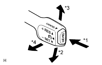
| *1 | ON/OFF |
| *2 | - SET |
| *3 | + RES |
| *4 | CANCEL |
| Result | Proceed to |
| OK | A |
| NG (All items are defective) | B |
| NG (1 to 3 items are defective) | C |
|
| ||||
|
| ||||
| A | ||
| ||
| 2.INSPECT CRUISE CONTROL MAIN SWITCH |
Remove the cruise control main switch (Click here).
Measure the resistance according to the value(s) in the table below.
| Tester Connection | Switch Condition | Specified Condition |
| 1 - 3 | Main switch off*1 | 1 MΩ or higher |
| Main switch on | Below 2.5 Ω | |
| + RES | 235 to 245 Ω | |
| - SET | 617 to 643 Ω | |
| CANCEL | 1509 to 1571 Ω |
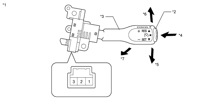
| *1 | Component without harness connected (Cruise Control Main Switch) | *2 | Main Switch |
| *3 | Lever | *4 | ON-OFF |
| *5 | - SET | *6 | + RES |
| *7 | CANCEL | - | - |
Reinstall the cruise control main switch (Click here).
|
| ||||
| OK | |
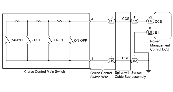
| 3.CHECK HARNESS AND CONNECTOR (CRUISE CONTROL MAIN SWITCH - SPIRAL CABLE SUB-ASSEMBLY) |
 |
Disconnect the connector from the spiral with sensor cable sub-assembly.
Disconnect the connector from the cruise control main switch.
Measure the resistance according to the value(s) in the table below.
| Tester Connection | Condition | Specified Condition |
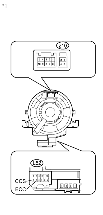
| Cruise control main switch side connector terminal 3 - z10-3 | Always | Below 1 Ω |
| Cruise control main switch side connector terminal 1 - z10-4 | Always | Below 1 Ω |
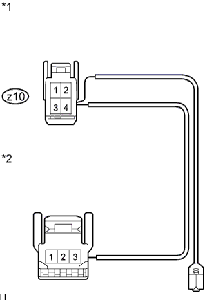
| *1 | Front view of wire harness connector (to Spiral with Sensor Cable Sub-assembly) |
| *2 | Front view of wire harness connector (to Cruise Control Main Switch) |
Reconnect the connector to the cruise control main switch.
Reconnect the connector to the spiral with sensor cable sub-assembly.
|
| ||||
| OK | |
| 4.CHECK SPIRAL WITH SENSOR CABLE SUB-ASSEMBLY |
 |
Remove the spiral with sensor cable sub-assembly (Click here).
Measure the resistance according to the value(s) in the table below.
| Tester Connection | Condition | Specified Condition |
| z10-3 - L52-1 (CCS) | The spiral with sensor cable sub-assembly is centered | Below 1 Ω |
| The spiral with sensor cable sub-assembly position is 2.5 rotations to the left | ||
| The spiral with sensor cable sub-assembly position is 2.5 rotations to the right | ||
| z10-4 - L52-2 (ECC) | The spiral with sensor cable sub-assembly is centered | Below 1 Ω |
| The spiral with sensor cable sub-assembly position is 2.5 rotations to the left | ||
| The spiral with sensor cable sub-assembly position is 2.5 rotations to the right |
| *1 | Component without harness connected (Spiral with Sensor Cable Sub-assembly) |
Reinstall the spiral with sensor cable sub-assembly (Click here).
|
| ||||
| OK | |
| 5.CHECK HARNESS AND CONNECTOR (SPIRAL CABLE SUB-ASSEMBLY - POWER MANAGEMENT CONTROL ECU) |
Disconnect the power management control ECU connector.
Disconnect the spiral with sensor cable sub-assembly connector.
 |
Measure the resistance according to the value(s) in the table below.
| Tester Connection | Condition | Specified Condition |
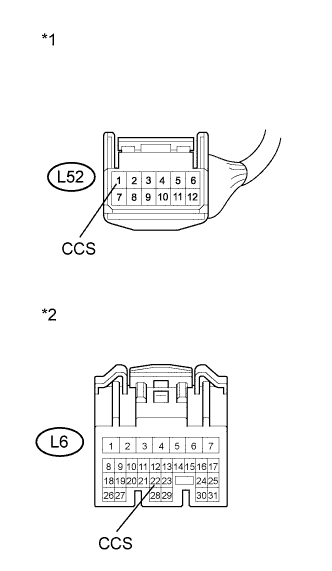
| L52-1 (CCS) - L6-22 (CCS) | Always | Below 1 Ω |
| Tester Connection | Condition | Specified Condition |
| L52-1 (CCS) or L6-22 (CCS) - Body ground | Always | 10 kΩ or higher |
| *1 | Front view of wire harness connector (to Spiral with Sensor Cable Sub-assembly) |
| *2 | Front view of wire harness connector (to Power Management Control ECU) |
Reconnect the spiral with sensor cable sub-assembly connector.
Reconnect the power management control ECU connector.
|
| ||||
| OK | |
| 6.CHECK HARNESS AND CONNECTOR (SPIRAL WITH SENSOR CABLE SUB-ASSEMBLY - BODY GROUND) |
 |
Disconnect the spiral with sensor cable sub-assembly connector.
Measure the resistance according to the value(s) in the table below.
| Tester Connection | Condition | Specified Condition |
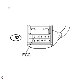
| L52-2 (ECC) - Body ground | Always | Below 1 Ω |
| *1 | Front view of wire harness connector (to Spiral with Sensor Cable Sub-assembly) |
Reconnect the spiral with sensor cable sub-assembly connector.
|
| ||||
| OK | ||
| ||
