Home

Toyota Workshop

GSIC - Global Service Information Center

DTC    P0112    Intake Air Temperature Circuit Low Input

DTC    P0113    Intake Air Temperature Circuit High Input

for Preparation Click here


DESCRIPTION

A190753E07
  1. The intake air temperature sensor, mounted in the mass air flow meter sub-assembly, monitors the intake air temperature. The intake air temperature sensor has a built-in thermistor with a resistance that varies according to the temperature of the intake air. When the intake air temperature becomes low, the resistance of the thermistor increases. When the temperature becomes high, the resistance drops. These variations in resistance are transmitted to the ECM as voltage changes (see Fig. 1).
  2. The intake air temperature sensor is powered by a 5 V supply from the THA terminal of the ECM, via resistor R which is located inside the ECM.
  3. Resistor R and the intake air temperature sensor are connected in series. When the resistance value of the intake air temperature sensor changes, according to changes in the intake air temperature, the voltage at terminal THA also varies. Based on this signal, the ECM increases the fuel injection volume when the engine is cold to improve driveability.

    HINT:
    When either of DTC P0112 or P0113 is stored, the ECM enters fail-safe mode. During fail-safe mode, the intake air temperature is estimated to be 20°C (68°F) by the ECM. Fail-safe mode continues until a pass condition is detected.


DTC No.
DTC Detection Condition
Trouble Area
P0112
Short in intake air temperature sensor circuit for 0.5 seconds
(1 trip detection logic)
  1. Short in intake air temperature sensor circuit
  2. Intake air temperature sensor (built into mass air flow meter sub-assembly)
  3. ECM
P0113
Open in intake air temperature sensor circuit for 0.5 seconds
(1 trip detection logic)
  1. Open in intake air temperature sensor circuit
  2. Intake air temperature sensor (built into mass air flow meter sub-assembly)
  3. ECM

HINT:
When any of these DTCs are set, check the intake air temperature by entering the following menus: Powertrain / Engine and ECT / Data List / All Data / Intake Air.

Temperature Displayed
Malfunction
-40°C (-40°F)
Open circuit
140°C (284°F)
Short circuit


WIRING DIAGRAM


A220564E01


INSPECTION PROCEDURE

HINT:
Read freeze frame data using the intelligent tester. The ECM records vehicle and driving condition information as freeze frame data the moment a DTC is stored. When troubleshooting, freeze frame data can help determine if the vehicle was moving or stationary, if the engine was warmed up or not, if the air fuel ratio was lean or rich, and other data from the time the malfunction occurred.

1.READ VALUE USING INTELLIGENT TESTER (INTAKE AIR)
  1. Connect the intelligent tester to the DLC3.

  1. Turn the power switch on (IG).

  1. Turn the tester on.

  1. Enter the following menus: Powertrain / Engine and ECT / Data List / All Data / Intake Air.

  1. Read the value displayed on the tester.

    OK:
    Same as actual intake air temperature.


    Result 
    Result
    Proceed to
    -40°C (-40°F)
    A
    140°C (284°F)
    B
    Same as actual intake air temperature
    C

    HINT:
    1. If there is an open circuit, the intelligent tester indicates -40°C (-40°F).
    1. If there is a short circuit, the intelligent tester indicates 140°C (284°F).


B
Go to step 4

C
CHECK FOR INTERMITTENT PROBLEMS (Click here)
A


2.READ VALUE USING INTELLIGENT TESTER (CHECK FOR OPEN IN WIRE HARNESS)


  1. Confirm good connection at the mass air flow meter sub-assembly.
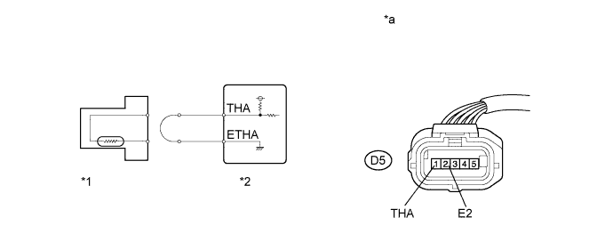

    A289412E01


Text in Illustration 
*1
Mass Air Flow Meter Sub-assembly
*2
ECM
*a
Front view of wire harness connector
(to Mass Air Flow Meter Sub-assembly)
-
-
  1. Disconnect the mass air flow meter sub-assembly connector.

  1. Connect terminals 1 (THA) and 2 (E2) of the mass air flow meter sub-assembly connector on the wire harness side.

  1. Connect the intelligent tester to the DLC3.

  1. Turn the power switch on (IG).

  1. Turn the tester on.

  1. Enter the following menus: Powertrain / Engine and ECT / Data List / All Data / Intake Air.

  1. Read the value displayed on the tester.

    Standard:
    140°C (284°F)

  1. Reconnect the mass air flow meter sub-assembly connector.


NG
Go to step 3
OK

REPLACE MASS AIR FLOW METER SUB-ASSEMBLY (Click here)  

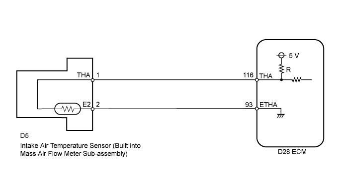
3.CHECK HARNESS AND CONNECTOR (MASS AIR FLOW METER SUB-ASSEMBLY - ECM)
  1. Disconnect the mass air flow meter sub-assembly connector.

  1. Disconnect the ECM connector.

  1. Measure the resistance according to the value(s) in the table below.

    Standard Resistance (Check for Open):

    Tester Connection
    Condition
    Specified Condition
    D5-1 (THA) - D28-116 (THA)
    Always
    Below 1 Ω
    D5-2 (E2) - D28-93 (ETHA)
    Always
    Below 1 Ω

  1. Reconnect the mass air flow meter sub-assembly connector.

  1. Reconnect the ECM connector.


NG
REPAIR OR REPLACE HARNESS OR CONNECTOR (MASS AIR FLOW METER SUB-ASSEMBLY - ECM)
OK

REPLACE ECM (Click here)  

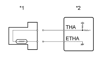
4.READ VALUE USING INTELLIGENT TESTER (CHECK FOR SHORT IN WIRE HARNESS)


    A255925E01
  1. Disconnect the mass air flow meter sub-assembly connector.
    Text in Illustration 
    *1
    Mass Air Flow Meter Sub-assembly
    *2
    ECM

  1. Connect the intelligent tester to the DLC3.

  1. Turn the power switch on (IG).

  1. Turn the tester on.

  1. Enter the following menus: Powertrain / Engine and ECT / Intake Air.

  1. Read the value displayed on the tester.

    Standard value:
    -40°C (-40°F)

  1. Reconnect the mass air flow meter sub-assembly connector.


NG
Go to step 5
OK

REPLACE MASS AIR FLOW METER SUB-ASSEMBLY (Click here)  

5.CHECK HARNESS AND CONNECTOR (MASS AIR FLOW METER SUB-ASSEMBLY - ECM)
  1. Disconnect the mass air flow meter sub-assembly connector.

  1. Disconnect the ECM connector.

  1. Measure the resistance according to the value(s) in the table below.

    Standard Resistance (Check for Short):

    Tester Connection
    Condition
    Specified Condition
    D5-1 (THA) or D28-116 (THA) - Body ground
    Always
    10 kΩ or higher

  1. Reconnect the mass air flow meter sub-assembly connector.

  1. Reconnect the ECM connector.


NG
REPAIR OR REPLACE HARNESS OR CONNECTOR (MASS AIR FLOW METER SUB-ASSEMBLY - ECM)
OK

REPLACE ECM (Click here)