Home

Toyota Workshop

GSIC - Global Service Information Center

HYBRID CONTROL SYSTEM > DIAGNOSIS SYSTEM

for Preparation Click here


DESCRIPTION


  1. The power management control ECU (HV CPU) has a self-diagnosis system. If the computer, hybrid vehicle control system, or a component is not working properly, the ECU records the conditions that relate to the fault. The ECU also illuminates the master warning light in the combination meter and provides other appropriate messages on the multi-information display, such as the HV system warning message, the HV battery warning message, on the discharge warning message.


    A221007E01

    HINT:
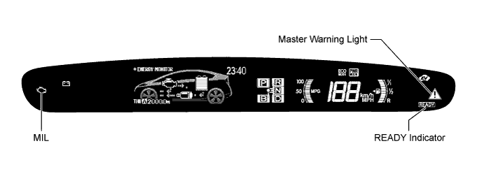
    The master warning light will illuminate when the hybrid vehicle control system malfunctions and the light will blink when in inspection mode.

  2. Description for Euro-OBD (European spec.)

    1. When troubleshooting Euro-OBD vehicles, the only difference from the usual troubleshooting procedure is that you need to connect the OBD scan tool complying with ISO 15031-4 or the intelligent tester to the vehicle, and read various data output from the vehicle's ECUs.
    2. Euro-OBD regulations require that the vehicle's on-board computer illuminates the MIL in the instrument panel when the computer detects malfunction in: 1) the emission control systems/components, or 2) the powertrain control components (which affect vehicle emissions), or 3) the computers. In addition, the applicable Diagnosis Trouble Codes (DTCs) prescribed by ISO 15031-4 are recorded in the power management control ECU memory (Click here).
    3. To check the DTCs, connect the intelligent tester or OBD scan tool to the Data Link Connector 3 (DLC3) of the vehicle. The intelligent tester or OBD scan tool also enables you to erase the DTCs and check the freeze frame data and various forms of the HV battery systems data (for operating instructions, refer to their respective instruction manuals). The DTCs include ISO controlled codes and manufacturer controlled codes. ISO controlled codes must be set as prescribed by the ISO, while manufacturer controlled codes can be set by a manufacturer within the prescribed limits (Click here).
    4. Freeze frame data:
      The Freeze frame data records the driving condition when malfunction is detected. When troubleshooting, it can help determine if the vehicle was running, braked, stopped, or reversed.
    If the malfunction does not recur in 3 consecutive trips, the MIL will go off automatically. However the DTCs remain recorded in the power management control ECU memory.


2 TRIP DETECTION LOGIC
  1. When a malfunction is first detected, the malfunction is temporarily stored in the power management control ECU (HV CPU) memory (1st trip). If the same malfunction is detected during the next drive cycle, the MIL is illuminated (2nd trip).

FREEZE FRAME DATA
  1. The power management control ECU (HV CPU) records vehicle and driving condition information as freeze frame data the moment a DTC is stored. When troubleshooting, freeze frame data can be helpful in determining whether the vehicle was running or stopped, whether the engine was warmed up or not, as well as other data recorded at the time of a malfunction.

AUXILIARY BATTERY VOLTAGE

Standard Voltage:
Switch Condition
Specified Condition
Power switch on (IG)
11 to 14 V

  1. If voltage is below 11 V, replace or recharge the battery.

MIL (Malfunction Indicator Lamp)
  1. The MIL is illuminated when the power switch is first turned on (IG), before the READY indicator comes on.

  2. When the READY indicator turns on, the MIL should turn off. If the MIL remains illuminated, the diagnosis system has detected a malfunction or abnormality in the system.

    HINT:
    If the MIL is not illuminated when the power switch is first turned on (IG), check the MIL circuit (Click here).