FRONT SUSPENSION MEMBER > INSTALLATION |
| 1. TEMPORARILY TIGHTEN FRONT NO. 1 LOWER SUSPENSION ARM SUB-ASSEMBLY LH |
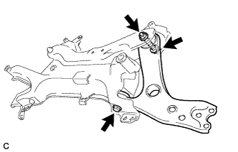 |
Temporarily tighten the front No. 1 lower suspension arm sub-assembly LH to the front suspension crossmember with the 2 bolts and nut.
| 2. TEMPORARILY TIGHTEN FRONT NO. 1 LOWER SUSPENSION ARM SUB-ASSEMBLY RH |
| 3. INSTALL STEERING LINK ASSEMBLY |
 |
Install the steering link assembly to the front suspension crossmember sub-assembly with the 2 bolts and 2 nuts.
| 4. INSTALL FRONT STABILIZER BAR |
Install the front stabilizer bar to the front suspension crossmember sub-assembly so that the identification mark is positioned on the right side of the vehicle.
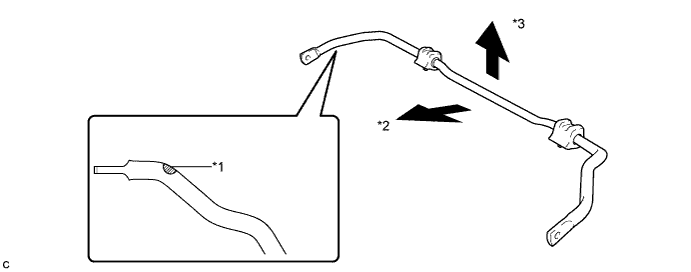
| *1 | Identification Mark | *2 | Front of the Vehicle |
| *3 | Top of the Vehicle | - | - |
| 5. INSTALL FRONT SUSPENSION MEMBER FRONT BRACE LH |
 |
Install the front suspension member front brace LH with the 4 bolts.
| *1 | Protrusion |
| 6. INSTALL FRONT SUSPENSION MEMBER FRONT BRACE RH |
 |
Install the front suspension member front brace RH with the 4 bolts.
| *1 | Protrusion |
| 7. INSTALL FRONT CROSS MEMBER SUB-ASSEMBLY |
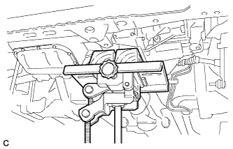 |
Using a transmission jack, support the engine assembly with transaxle.
 |
Install the front cross member sub-assembly with the 4 bolts.
 |
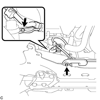
Connect the engine mounting insulator with the 2 bolts.
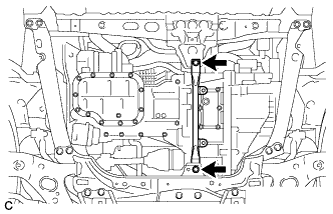
| 8. INSTALL FRONT SUSPENSION CROSSMEMBER SUB-ASSEMBLY |
 |
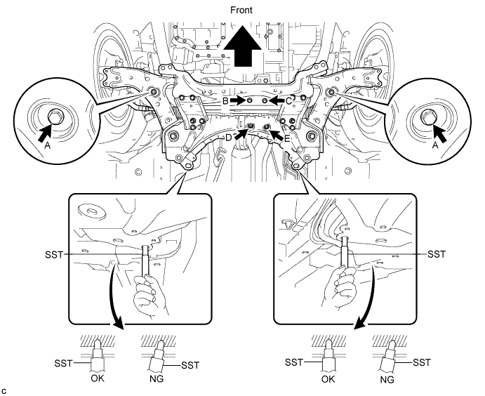
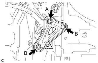
Support the front suspension crossmember with a transmission jack.
While inserting SST into the reference holes on the front suspension crossmember RH and LH alternately, tighten 2 bolts A, 2 bolts B, C and 2 nuts on the RH and LH sides to the respective specified torque in several steps.
 |
Install the 2 wire harness clamp brackets with the 2 bolts.
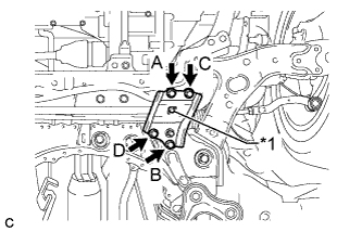
| 9. INSTALL FRONT SUSPENSION MEMBER REAR BRACE LH |
 |
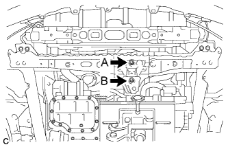
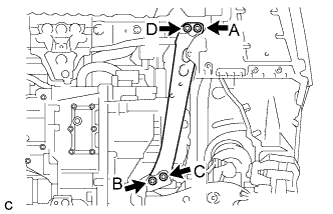
Install the front suspension member rear brace LH with the 2 bolts B and bolt A.
Install the clip.
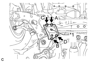
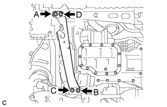
| 10. INSTALL FRONT SUSPENSION MEMBER REAR BRACE RH |
| 11. INSTALL REAR SIDE RAIL REINFORCEMENT SUB-ASSEMBLY LH |
 |
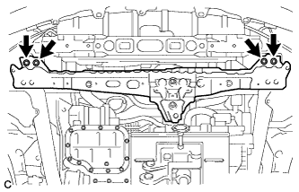
Install the rear side rail reinforcement sub-assembly LH with the 4 bolts.
| 12. INSTALL REAR SIDE RAIL REINFORCEMENT SUB-ASSEMBLY RH |
 |
Install the rear side rail reinforcement sub-assembly RH with the 4 bolts.
| 13. INSTALL FRONT ENGINE MOUNTING BRACKET LOWER REINFORCEMENT |
 |
Install the front engine mounting bracket lower reinforcement with the 2 bolts.
| 14. CONNECT FRONT NO. 1 LOWER SUSPENSION ARM SUB-ASSEMBLY LH |
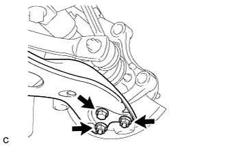 |
Install the front No. 1 lower suspension arm sub-assembly to the front lower ball joint with the bolt and 2 nuts.
| 15. CONNECT FRONT NO. 1 LOWER SUSPENSION ARM SUB-ASSEMBLY RH |
| 16. CONNECT TIE ROD END SUB-ASSEMBLY LH |
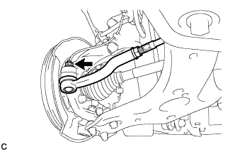 |
Connect the tie rod end sub-assembly LH to the steering knuckle with the nut.
Install a new clip.
| 17. CONNECT TIE ROD END SUB-ASSEMBLY RH |
| 18. INSTALL FRONT STABILIZER LINK ASSEMBLY LH |
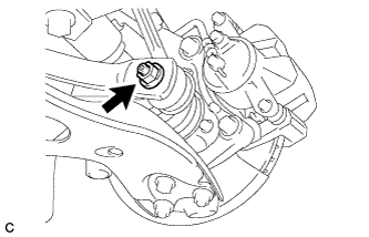 |
Install the front stabilizer link assembly LH to the front stabilizer bar with the nut.
| 19. INSTALL FRONT STABILIZER LINK ASSEMBLY RH |
| 20. CONNECT NO. 1 STEERING COLUMN HOLE COVER SUB-ASSEMBLY |
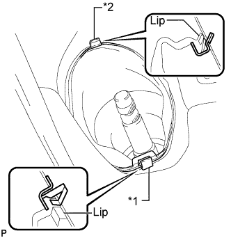 |
Place clip A as shown in the illustration and engage clip B to the body to connect the No. 1 steering column hole cover sub-assembly.
| *1 | Clip A |
| *2 | Clip B |
| 21. CONNECT NO. 2 STEERING INTERMEDIATE SHAFT ASSEMBLY |
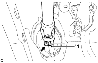 |
Align the matchmarks on the No. 2 steering intermediate shaft assembly and steering intermediate shaft to connect the No. 2 steering intermediate shaft assembly to the steering intermediate shaft.
| *1 | Matchmark |
Install the bolt.
| 22. INSTALL COLUMN HOLE COVER SILENCER SHEET |
 |
Install the column hole cover silencer sheet with the 2 clips.
Install the floor carpet.
| 23. INSTALL FRONT WHEELS |
| 24. STABILIZE SUSPENSION |
Lower the vehicle.
Press down on the vehicle several times to stabilize the suspension.
| 25. FULLY TIGHTEN FRONT NO. 1 LOWER SUSPENSION ARM SUB-ASSEMBLY LH |
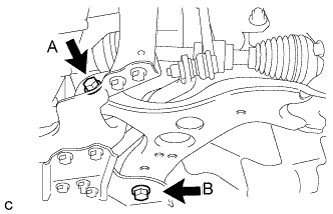 |
Fully tighten the bolt A and B.
| 26. FULLY TIGHTEN FRONT NO. 1 LOWER SUSPENSION ARM SUB-ASSEMBLY RH |
| 27. INSTALL FRONT LOWER BUMPER ABSORBER |
| 28. INSTALL FRONT SPOILER COVER (w/ Front Spoiler) |
| 29. INSTALL REAR ENGINE UNDER COVER LH |
| 30. INSTALL REAR ENGINE UNDER COVER RH |
| 31. INSTALL FRONT NO. 3 ENGINE UNDER COVER |
| 32. INSTALL NO. 2 ENGINE UNDER COVER |
| 33. INSTALL NO. 1 ENGINE UNDER COVER |
| 34. INSPECT AND ADJUST FRONT WHEEL ALIGNMENT |
